High-Speed Optical Transceiver Validation & Testing
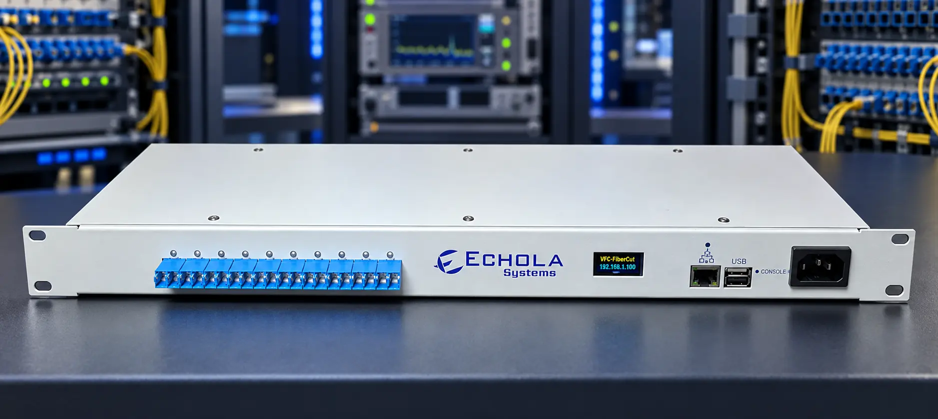
Variable Optical Attenuators (VOAs) enable controlled, repeatable changes in optical power without changing the link's electrical interfaces or communication protocol. They are useful in optical transceiver development, network equipment validation, production testing, and R&D laboratories, including work on 800G and emerging 1.6T optical interfaces. By gradually increasing attenuation, engineers can characterize receiver performance, identify link margins, and observe how high-speed connections behave as optical power falls.
These measurements are especially important when validating high-speed Ethernet links, including 400G, 800G, and emerging 1.6T interfaces, as well as InfiniBand, Fibre Channel, and optical transport links. A programmable VOA introduces a known or repeatable optical impairment, while the transceiver, network equipment, or external test instruments measure the resulting behavior.
Optical Transceiver and Receiver Validation
As data rates increase to 800G and 1.6T, link budgets and FEC behavior deserve careful validation. An optical receiver must maintain acceptable performance across its specified received-power range. Programmable attenuation makes it possible to test that range systematically rather than manually swapping fixed attenuators.
- Receiver sensitivity: Increase attenuation in controlled steps and determine the received optical power at which the receiver reaches a specified BER or other performance threshold.
- BER versus optical power: Correlate attenuation steps with bit error rate (BER) obtained from a bit-error-rate tester (BERT) or compatible network test equipment.
- Forward error correction (FEC): Monitor available pre-FEC and post-FEC error counters as optical power decreases to evaluate correction behavior and failure thresholds.
- Link margin: Determine how much additional optical loss a working connection can tolerate before errors exceed a limit or the link drops.
- Loss and recovery: Apply a gradual power reduction or a larger attenuation step, then restore the signal and observe link alarms, stability, and recovery time.
VOAs are optically data-rate transparent within their specified wavelength and impairment limits. Actual 800G/1.6T validation requires compatible transceivers and test instruments, and verification of the optical interface (including any parallel fiber or WDM lanes).
For calibrated sensitivity or receiver-power results in dBm, the test setup should include a suitable optical power measurement and wavelength-specific calibration. The VOA controls attenuation; it does not itself measure BER, FEC, or receiver power.
A Typical Automated Test Sequence
- Connect the optical transmitter to the receiver through a programmable VOA and establish a baseline link.
- Measure or establish a reference optical power and select attenuation increments and dwell times.
- Step attenuation through the desired range using a remote-control interface.
- At each step, collect BER, FEC, receiver diagnostics, and link-state data from compatible external equipment.
- Restore attenuation to the baseline setting and check link recovery or repeatability.
- Generate a report showing performance versus attenuation or measured received power.
This approach supports unattended regression testing, comparative transceiver evaluation, and repeatable characterization across multiple devices under test.
Beyond Transceiver Testing: Other VOA Applications
- Optical network equipment qualification: Introduce controlled link degradation to validate alarms, protection switching, and reconnection behavior.
- High-speed data center link testing: Explore available optical margin in Ethernet or InfiniBand interconnects, including links between switches and compute racks.
- Optical power equalization: Set or balance optical power levels in laboratory setups and applications where controlled attenuation is necessary.
- Stress and regression testing: Repeat attenuation profiles to compare firmware, hardware revisions, or transceiver suppliers under consistent optical conditions.
- Teaching and optical research: Demonstrate receiver thresholds, power budgets, and loss-induced performance changes.
How Echola Systems Supports VOA-Based Testing
Echola Systems offers remotely controlled optical products for test automation and network validation. The VFC series combines fiber-cut simulation with MEMS variable attenuation, making it useful for both failover testing and repeatable optical link impairment. For applications requiring dedicated or more precise optical attenuation control, the AttenuX product family is another option.
Remote management and programmable control allow users to coordinate attenuation changes with external test instruments and device telemetry. This helps automate sensitivity sweeps, BER/FEC measurements, link-margin exploration, and recovery tests without repeatedly modifying the physical fiber setup.
Choosing the Right Test Configuration
Use VFC when the workflow combines controllable signal degradation with optical interruption and recovery testing. Consider a dedicated calibrated VOA setup when the primary goal is quantitative receiver sensitivity, precise attenuation sweeps, or repeatable optical power characterization. In both cases, choose the appropriate single-mode or multimode hardware and confirm the operating wavelength, attenuation range, accuracy, and optical loss budget for the transceiver under test.